When it comes to Smart Vision Lights, the most common issue we see is that customers may forget to wire the Intensity Pin or the Trigger Pin.
Understanding Operation Modes
Most Lights from Smart Vision can be operated in "Constant On" Operation, or "Strobe" Operation.
Constant On - The Light is always on
Benefits - Always On, No Synchronization Needed with Camera Trigger
Drawbacks - Lower Light Intensity, Motion Blur in moving objects
Use Case - When objects are stationary or moving at slow speeds
Strobe - The Light is only on for a very brief period of time (nanoseconds - milliseconds)
Benefits - Significantly brighter output (measured in LUX) when compared to Constant On Operation
Drawbacks - Must be timed/synchronized with Camera (not very difficult); May be frustrating or even hazardous to operators when exposed to constant strobing without proper protection.
Use Case - When objects are in motion
Lights with "Multi Drive" Drivers can be strobed or operated in constant on.
Lights with "Over Drive" Drivers can ONLY be strobed.
Economy Lights and T-Slot Lights can only be operated in Constant On Operation
Cable Pinout
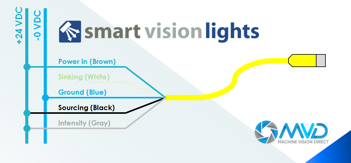
Virtually all Smart Vision Lights utilize a 5-Pin M12 Industry Standard Connector. Machine Vision Direct recommends using the 5PM12 Series Cables as they are designed to withstand the current requirements of Smart Vision Lights, including in high current situations such as when strobing.
The Pinout of the 5PM12 cable is as follows:

How to Wire for Constant Operation
Note: Only applicable to lights with MultiDrive, Economy Lights, and TSLOT Lights. Not Applicable to Lights with OverDrive Driver (Part No. Beginning with "OD")
There are two ways to wire for constant operation - both result in the same, the light operating in constant on operation at maximum constant intensity
Constant Operation SOURCING Wiring (Most Common)

Brown, Black, and Gray are connected to 24 VDC
Blue is connected to 0 VDC
White is not connected (Never connect White and Black wire at the same time)
Constant Operation SINKING Wiring

Brown and Gray are connected to 24 VDC
Blue and White are connected to 0 VDC
Black is not connected (Never connect White and Black wire at the same time)
How to Wire for Strobe Operation
Note: Only applicable to lights with MultiDrive, and OverDrive Drivers. Not Applicable to Economy and T-Slot Lights
Strobe Operation SOURCING Wiring (Most Common)

Brown and Gray are connected to 24 VDC
Blue is connected to 0 VDC
Black is connected to Strobe Output from Camera (SOURCING OUTPUT)
White is not connected (Never connect White and Black wire at the same time)
Strobe Operation SINKING Wiring

Brown and Gray are connected to 24 VDC
Blue is connected to 0 VDC
White is connected to Strobe Output from Camera (SINKING OUTPUT)
Black is not connected (Never connect White and Black wire at the same time)
DIMMING LIGHTS
All wiring methods above reflect operating lights at maximum intensity. Usually the exposure of the camera can be reduced to accommodate the maximum intensity, but in many scenarios, it will still make sense to dim the light.
Certain lights (Such as the S75 Brick Light and L300 Bar Light) have built-in dimming capabilities and can be dimmed by adjusting the built-in potentiometer.
The majority of lights have 0-10V Intensity Control, in which case the IVP-C1 Intensity Control can be used to dim the lights. The IVP-C1 assembly is connected in series between the 5PM12 cable and the light.
Note: Not all lights can be dimmed. Economy Lights and TSLOT Lights are not capable of dimming, contact Machine Vision Direct for inquiries regarding specific lights.
Conclusion
Wiring lights is not difficult, and our application engineers are here to make your life easier. If there are any questions or if you continue to have issues, don't hesitate to reach out to Machine Vision Direct at Support@MachineVisionDirect.com or (331) 684-7466

